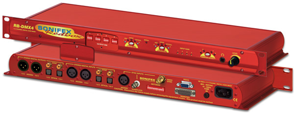
SONIFEX Redbox RB-DMX4
SONIFEX Redbox RB-DMX4
4 x 4 Channel Digital Audio Mixer/Router (1U)
RB-DMX4
£1,209.95 Price excludes VAT
Product lists can be submitted to HHB for a packaged quotation
The RB-DMX4 is a digital mixer capable of mixing or routing 4 mono input channels into 4 mono outputs, or 2 stereo inputs into 2 stereo outputs. The inputs are sample rate converted to allow sources of different sample rates to be mixed. The flexible Mix Matrix allows for a wide variety of mixing options and creativity, using 4 blocks of 4 way DIPswitches to select which inputs are mixed or routed to which outputs.
The RB-DMX4 has 4 x digital mono audio inputs, each one selectable in pairs via front panel INPUTS 1 & 2 and INPUTS 3 & 4 push buttons, from either AES/EBU balanced XLRs, S/PDIF unbalanced phonos or TOSlink unbalanced optical inputs. Sample rate converters on each input mean that sources of different sample rates can be used with the output sample rate being defined independently. The colour of the INPUTS 1 & 2 and INPUTS 3 & 4 push-buttons indicate whether the input source is synchronised (no colour) or not (flashing green and red).
Each input has a trim pot, which can be used to attenuate the input signal. This allows for a perfect mix of channels at different audio levels. Audio presence LEDS around each input button give an indication of input audio level. There is one LED for each channel. There are also 4 presence LEDS around the MONITOR button which give an indication of output level. Additional gain can be added by accessing the OUTPUT GAIN mode.
There are 2 stereo outputs which are available as simultaneous AES/EBU balanced XLRs, S/PDIF unbalanced phonos or TOSlink unbalanced optical outputs. The output sample rates are selectable via rear panel DIPswitches from one of 32kHz, 44.1kHz, 48kHz, 88.2kHz, 96kHz, 176.4kHz or192kHz.
The unit has TTL wordclock BNC and AES/EBU XLR synchronising inputs as standard and optionally, the
RB-SYA and RB-SYD synchronisation boards can be fitted to synchronise the unit to analogue or digital video signals. A rear panel DIPswitch block is used to decide whether the unit is synchronised to Input1, Input2, the AES/EBU sync input, the wordclock sync input or an optional video sync board. The DIPswitch block also selects the synchronisation mode of the unit and the MONITOR button flashes whenever the unit is not synchronised to an incoming sync signal. Selectable sync modes are as follows:
Master Mode
In this mode the digital output sample rate is simply set by, and locked to, the internal on-board clock generator. No sync signal is used or required.
Auto Sync Mode
In this mode the digital output sample rate follows the selected sync input. When the sync signal is not present the output sample rate will be set by, and locked to, the internal on-board clock generator at the selected output frequency.
Auto Lock Mode
In this mode no output is generated until lock is achieved with a sync signal. The digital output sample rate now follows the sync input. If the sync signal is removed then the output sample rate will be set by, and locked to, the internal on-board clock generator at the closest frequency available to the previous sync input.
Slave Mode
In this mode the digital output sample rate follows the sync input. When the sync signal is not present the digital output is turned off.
There is a monitor socket on the front panel with a gain pot to allow you to monitor the output of each channel. The monitored channel can be selected via a push button on the front panel which, when held can also supply up to 12dB of gain. If the level that is being monitored is close to full scale, a 12dB attenuation can be added to the monitor channel via a DIPswitch on the rear panel.
The unit can be placed in mono or stereo mode via rear panel DIPswitch. Stereo mode allows you to monitor the two input pairs as stereo channels as well as controlling the input gain as a pair, giving tied audio levels.
The RB-DMX4 has been designed to have a passive signal path through the main input, so if power to the unit fails, signal inputs 1 & 2 are routed to outputs 1 & 2 and signal inputs 3 & 4 are routed to outputs 3 & 4. This is essential for applications such as installation at transmitter sites, where a power failure to the unit should not prevent the audio input signal from being output to the transmitter. Please note that this is not true for the TOSLink outputs which are muted.


